One day I had a consultancy work assisting a client doing a drone survey and processing the data. When he finished
creating contour line using QGIS, he asked me: How to convert the contour into CAD file? While smiling I told him, "Just export it and save it as AutoCAD DXF file, and the process will run". After a few minutes he replied. "Why all contour lines are flat with
zero elevation?". What?? How could it be? Then I tried it my self, using other tools while
thinking what's wrong. But still no elevation information in the output CAD
file. It was a very short story and now you know the story behind this
post :).
So, what happened exactly? Why the CAD file has no elevation? That's because the shapefile's geometry is in 2D vector mode. We know that a shapefile consist of several files with different extension such as
dbf,
shp,
prj and
shx. The geometry data with coordinate information are stored in
shp file extension with x and y coordinate that construct the data. If a shapefile is in 2D vector mode, it just has x,y coordinate. That's why when it is exported into CAD, no elevation information will be exported, because physically there is no elevation information in the data, although it has an elevation column in the attribute table. To make it, we have to convert the data into 3D vector mode and assign elevation information for z. To know more about shapefile please refer to
ESRI shapefile technical description.
Then how to export a shapefile into a CAD dxf file without losing elevation information? Let's do it step by step using QGIS 3. For this tutorial I'm using QGIS 3.4.
1. Open a shapefile data in a projected coordinate system like UTM which has elevation information i.e. contour lines. I had one as in figure 1. Figure 2 shows the attribute table of the data. We can see it has ELEV column which stores elevation information. If we export the data before converting into 3D vector, the ELEV column will be gone.
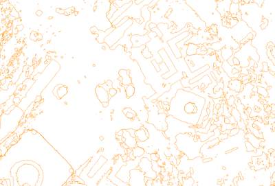 |
| Figure 1. Contour shapefile |
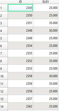 |
| Figure 2. Contour attribute table |
2. Now let's convert the shapefile into 3D vector using a tool from GRASS called v.to.3d. The tool can be found in the processing toolbox. In the search box type "3d", the tool will be shown under GRASS tool as in figure 3.
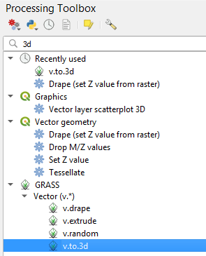 |
| Figure 3. GRASS vector to 3D tool |
3. Open the tool, it looks like figure 4. Firstly make sure to input the vector to be exported under the Name of input vector map. For Name of attribute column used for height, select the column which contains elevation information, for my case was ELEV column. Then under GRASS GIS 7 region extent select Use Layer Extent, so it will have the same extent with the input layer. Lastly save the shapefile of output 3D vector in your selected path. After pushing Run button the process is starting, the tab is switching to Log tab and we can see what's happening during the conversion.
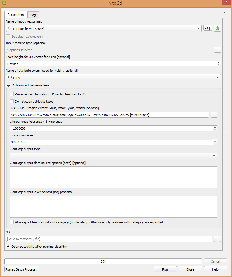 |
| Figure 4. Vector to 3D GRASS tool |
4. The converted 3D vector will be added to QGIS layer. Open the layer properties by right click the layer and choose Properties. The properties window will appear as in figure 5. Look at the
Geometry type, it should change to
Line(LineString25D). Before conversion the Geometry was
Line(MultiLineString).
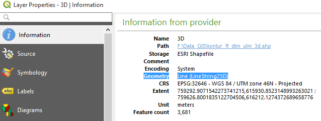 |
| Figure 5. Layer properties |
5. Now, it's ready to export the contour data to CAD dxf Format. Right click the 3D vector contour layer, select
Export then
Save Feature As..The save as window will show up like figure 6. Choose AutoCAD DXF for Format and specify the output path. In CRS option, the coordinate system of exported output CAD can be changed if it's required.
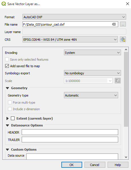 |
| Figure 6. Export tool SHP to DXF |
|
|
|
6. To try it, open the output DXF using a CAD software. Figure 7 shows the contour CAD data with x,y axis on the screen (z axis towards us). Figure 8 is the view of CAD data in x,z axis. In figure 8 we can see the contour lines are stacked respectively based on it's elevation. It means all the contour lines have elevation or height value.
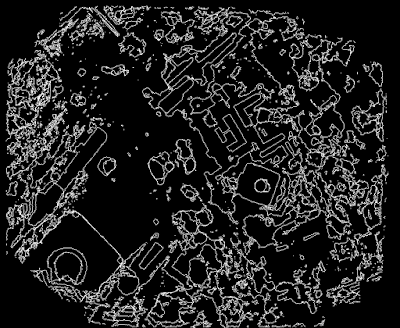 |
| Figure 7. CAD contour file view in x,y coordinate |
 |
| Figure 8. CAD contour file view in x,z coordinate |
That's all the tutorial how to export shapefile to CAD using QGIS and keep the elevation data. For conclusion I want to summarize. A shapefile in 2D vector mode only stores x,y coordinate without z value. To enable z information into CAD file after shapefile export operation, firstly it must be converted into 3D vector. It can be done using GRASS v.to.3d tool.
CAD
QGIS
Tutorial


